EK-TM4C123GXL - Configure the I2C Module to Transmit a Single Byte as a Master
Name of this blog post is the name of chapter 16.4.1 from ARM Cortex M4 TM4C123GH6PM
microcontroller datasheet (MCU on EK-TM4C123GXL board).
It will be showed how to setup I2C1 from scratch. There is a way to do this with functions for set registers parameters but in this blog post, it will be done by writing directly into the register address. It is decided that way because it is the way how drivers are done.
The EK-TM4C123GXL has support for 4 I2C serial computer buses. First, we need to unlock GPIO_PORTA register and I2C1 register. To do that we need to do that over System Control Register addresses.

Image 1 - System Control Register Map
1. Enable the I2C clock using the RCGCI2C register

Image 2 - Enabling register for I2C
//SYSCTL -> System Control Register
//RCGC -> Run Mode Clock Gating Control Register
#define SYSCTL_RCGCI2C 0x400FE620
#define SYSCTL_PRI2C 0x400FEA20
*(volatile uint32_t*)(SYSCTL_RCGCI2C) = 0x2;
volatile uint32_t value1 = (*(volatile uint32_t*)(SYSCTL_PRI2C));
while(!((value1 >> 1) & 0x1))
{} //wait until register is enabled
With SYSCTL_RCGCI2C registers, you can check if peripheral I2C1 is enabled.

3. In the GPIO module, enable the appropriate pins for their alternate function using the
Now we are ready to set I2C1 SCL to connector PA6 and I2C1 SDA to connector PA7.
We need to setup several registers.

It is not mentioned inside datasheet but pins also need to be set as digital pins, so here is how to enable digital pins.
#define GPIO_PORTA_GPIOODR 0x4000450C
// Hex value 08 is for PIN 7
*(volatile uint32_t *)(GPIO_PORTA_GPIOODR) |= 0x00000080;
Hex value C0 is 11000000 binary. So it means it activate ports 7 and 6. Hex 80 activates only port 7.
5. Configure the PMCn fields in the GPIOPCTL register to assign the
After enabling peripherals, we need to set I2C1 to GPIO PORT A output with GPIO_PCTL port.

If you are using 10 K ohms pull-up resistor then the best frequency for usage is in the kHz.
For clock frequency in the MHz, it is recommended to use 1 K ohm resistors.
According to the calculation for 80 MHz system clock and 250 kHz, SCL calculated value for TPR register is hex 0xF.
Here this value is tested and reduced to hex 0xE because logical analyzer shows 250 kHz when the value is hex 0xE.


The I2C baud rate for 250 kHz SCL is 250 Kbps.

R/S value from register stays 0 for now because we are transmitting.
I2CMCS register has two roles. It accesses status bits when read and control bits when written. When read, the status
register indicates the state of the I2C bus controller. When written, the control register configures
the I2C controller operation.


For geting ACK you need conect slave. This was done for now without slave device, so no ACK is received.

2. Enable the clock to the appropriate GPIO module via the RCGCGPIO register

Image 3 - Enable register for GPIO PORT
#define SYSCTL_RCGCGPIO 0x400FE608
#define SYSCTL_PRGPIO 0x400FEA08
*(volatile uint32_t *)(SYSCTL_RCGCGPIO) = 0x1;
volatile uint32_t value2 = (*(volatile uint32_t*)(SYSCTL_PRGPIO));
while(!(value2 & 0x1))
{} //wait until registers are enabled
With SYSCTL_RCGCI2C register, you can check if peripheral GPIO PORT A is enabled.
3. In the GPIO module, enable the appropriate pins for their alternate function using the
GPIOAFSEL register
Now we are ready to set I2C1 SCL to connector PA6 and I2C1 SDA to connector PA7.
We need to setup several registers.

Image 4 - Registers for setup I2C SCL and SDA on GPIO ports
#define GPIO_PORTA_GPIOAFSEL 0x40004420
// Hex vale C0 is for PIN 6 and 7
*(volatile uint32_t *)(GPIO_PORTA_GPIOAFSEL) |= 0x000000C0;
// Hex vale C0 is for PIN 6 and 7
*(volatile uint32_t *)(GPIO_PORTA_GPIOAFSEL) |= 0x000000C0;
It is not mentioned inside datasheet but pins also need to be set as digital pins, so here is how to enable digital pins.
#define GPIO_PORTA_GPIODEN 0x4000451C
// Hex vale C0 is for PIN 6 and 7
*(volatile uint32_t *)(GPIO_PORTA_GPIODEN) |= 0x000000C0;
// Hex vale C0 is for PIN 6 and 7
*(volatile uint32_t *)(GPIO_PORTA_GPIODEN) |= 0x000000C0;
4. Enable the I2CSDA pin for open-drain operation
#define GPIO_PORTA_GPIOODR 0x4000450C
// Hex value 08 is for PIN 7
*(volatile uint32_t *)(GPIO_PORTA_GPIOODR) |= 0x00000080;
Hex value C0 is 11000000 binary. So it means it activate ports 7 and 6. Hex 80 activates only port 7.
You can read more about this setup in chapter "16.2 Signal Description" in the datasheet.
5. Configure the PMCn fields in the GPIOPCTL register to assign the
I2C signals to the appropriate pins
After enabling peripherals, we need to set I2C1 to GPIO PORT A output with GPIO_PCTL port.

Image 5 - Value that needs to be used to set I2C to GPIO PORT A
#define GPIO_PORTA_GPIO_PCTL 0x4000452C
// Set I2C1 SCL to PA6 and I2C1 SDA to PA7
*(volatile uint32_t *)(GPIO_PORTA_GPIO_PCTL) |= 0x33000000;
// Set I2C1 SCL to PA6 and I2C1 SDA to PA7
*(volatile uint32_t *)(GPIO_PORTA_GPIO_PCTL) |= 0x33000000;
6. Initialize the I2C Master by writing to I2CMCR register
#define I2C1_I2C_MCR 0x40021020//Master Function Enable
*(volatile uint32_t *)(I2C1_I2C_MCR) |= 0x00000010;
7. Set the desired SCL clock speed
If you are using 10 K ohms pull-up resistor then the best frequency for usage is in the kHz.
For clock frequency in the MHz, it is recommended to use 1 K ohm resistors.
According to the calculation for 80 MHz system clock and 250 kHz, SCL calculated value for TPR register is hex 0xF.
Here this value is tested and reduced to hex 0xE because logical analyzer shows 250 kHz when the value is hex 0xE.

#define I2C1_I2C_MTPR 0x4002100C
*(volatile uint32_t *)(I2C1_I2C_MTPR) = 0xE; //Set TPR value

Image 6 - I2C Clock measured with logic analyzer
The I2C baud rate for 250 kHz SCL is 250 Kbps.
8. Specify the slave address of the master and that the next operation is a Transmit
by writing to I2CMSA register
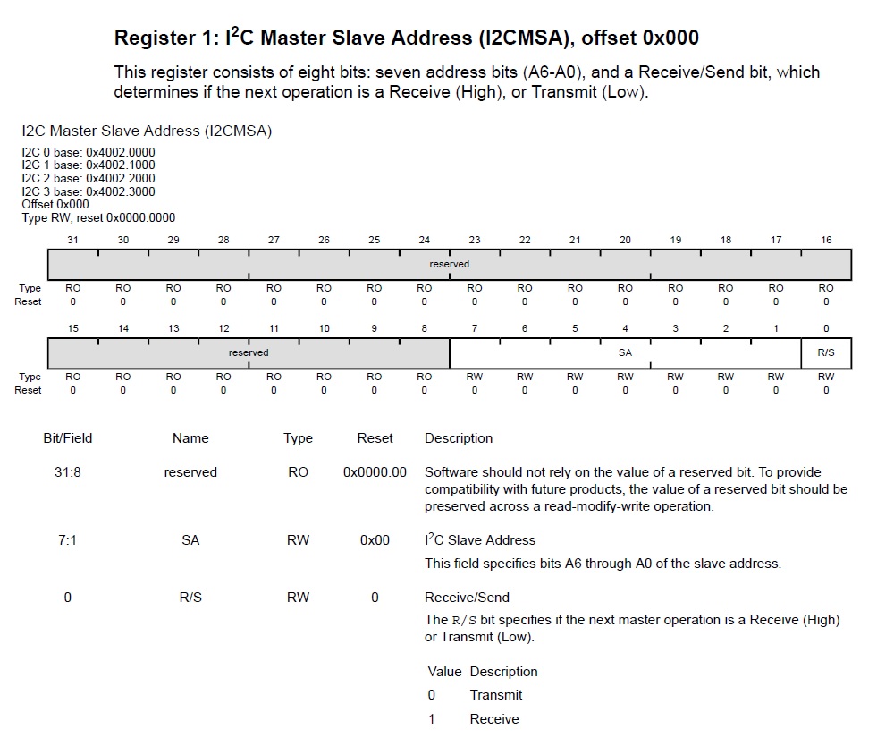
Image 7 - I2CMSA register
uint8_t slave_addr = 0x3B;
#define I2C1_I2C_MSA 0x40021000
#define I2C1_I2C_MSA 0x40021000
*(volatile uint32_t *)(I2C1_I2C_MSA) = slave_addr << 1;
9. Place data (byte) to be transmitted in the data register by writing to I2CMDR register

Image 8 - I2CMDR register
uint8_t data = 0x55;
#define I2C1_I2C_MDR 0x40021008
#define I2C1_I2C_MDR 0x40021008
*(volatile uint32_t *)(I2C1_I2C_MDR) = data;
10. Initiate a single byte transmit of the data from Master to Slave by writing to I2CMCS register
I2CMCS register has two roles. It accesses status bits when read and control bits when written. When read, the status
register indicates the state of the I2C bus controller. When written, the control register configures
the I2C controller operation.

Image 9 - I2CMCS register (Write only options)
#define I2C1_I2C_MCS 0x40021004
*(volatile uint32_t *)(I2C1_I2C_MCS) |= 0x3; // START & RUN
after data is sent you can stop it with:
#define I2C1_I2C_MCS 0x40021004
*(volatile uint32_t *)(I2C1_I2C_MCS) &= ~0x2; // remove START
*(volatile uint32_t *)(I2C1_I2C_MCS) |= 0x4; // STOP
11. Wait until the transmission completes by polling the I2CMCS register

Image 10 - I2CMCS register (Read only options)
Flag which we need to check is BUSBSY. It is on position 6 in MCS register.
#define I2C1_I2C_MCS 0x40021004
volatile uint32_t value = (*(volatile uint32_t *)(I2C1_I2C_MCS));value >>= 6;
while((value & 0x1)){}
while((value & 0x1)){}
12. Check the ERROR bit in the I2CMCS register to confirm the transmit was acknowledged
For geting ACK you need conect slave. This was done for now without slave device, so no ACK is received.

Image 11 - Logic Analyser for master sent
At image 9 you can see how master sent address 0x3B (with last bit 0 it is 0x76) and after that byte 0x55.


Comments
Post a Comment