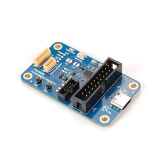
Posts

VL53L5CX-SATEL connect to Pixhawk

Image
This sensor has one of the worst documentation on the internet. It took me too long to start I2C communication with it so I decided to write the notes here. My initial goal was to write a driver for PX4 Autopilot, so here are my findings. I2C address The address 0x52 mentioned in VL53L5CX documentation is the one shifted to the left. So the real address is actually 0x29 . i2cdetect PX4 If you going to use the i2cdetect application from PX4 you will not be able to read any address because VL53L5CX doesn't respond with the ACK for some reason that I didn't investigate. Connecting the wires To connect wires you don't need to connect AVDD and PWREN to 5V.   The board has a 3.3V voltage regulator that turns 5V to 3.3V. You can reuse it to connect it to the EVK_IOVDD pin, so you don't need to wire an extra pin and it is very useful for a PX4 I2C standard connector. With this setup, you will be able to connect VL53L5CX to Pixhawk without the need for a 3.3V wire. If this save

STLink V3 + OpenOCD + STM32H747

Image
If you are running Linux and you instilled OpenOCD with sudo apt install openocd Make sure you check version with openocd --version If version is " Open On-Chip Debugger 0.11" there is very big chance your STLink V3 wan't connect to STM32H747 MCUs.    I got this error message: openocd -f /usr/share/openocd/scripts/interface/stlink.cfg -f /usr/share/openocd/scripts/target/stm32h7x.cfg            Open On-Chip Debugger 0.11.0 Licensed under GNU GPL v2 For bug reports, read        http://openocd.org/doc/doxygen/bugs.html Info : auto-selecting first available session transport "hla_swd". To override use 'transport select <transport>'. Info : The selected transport took over low-level target control. The results might differ compared to plain JTAG/SWD Info : Listening on port 6666 for tcl connections Info : Listening on port 4444 for telnet connections Info : clock speed 1800 kHz Error: open failed   Make sure to build latest OpenOCD. For me it start

Dell Alienware m17 R4 disassembly

Image
Needed to change the keyboard on my Dell Alienware m17 R4 and couldn't find images online to prepare myself for what will need to do when I started. So I took them while I was in the process of doing it, to help someone else in the future. And here are two advices before starting. 1) There is one connector where you need be extra careful. You can see it at image 1 with blue arrow. It is glued with black tape over it so don't try to remove it quickly or you will broke the upper plastic of the connector. Image 1 - week connector! 2) You will need very small screwdriver to remove keyboard at the end. Don't start with dissembling the laptop if you don't have one.   If this saves you some time or a connector, you can thank me by buying me a coffee.

Linuxdeployqt Icons missing in AppImage

Image
Recently I wanted to build a Gridcoin wallet in docker and everything was successful until I started a wallet and then noticed that icons were missing. That was strange because I didn't get any error while building it which I think is partial fault of Gridcoin itself. Figure 1 - Left is properly build AppImage with icons and right without icons It took me some time to figure out what was missing so here are steps that I have done. I was lucky enough that on my main machine, everything was working properly so I used --appimage-extract on both AppImages created in my machine and in docker and I compared the output. chmod +x Gridcoin.AppImage ./Gridcoin.AppImage --appimage-extract What I found out that docker ouput was missing iconengines plugin . So I installed libqt5svg5 with apt install -y libqt5svg5 and next time when I crated AppImage with: linuxdeployqt /Gridcoin-Research/build/src/qt/gridcoinresearch -appimage and when I started App icons showed up.  If you find this useful yo

Attaching to running PX4 1.14 + Gazebo Classic Typhoon h480

Image
Copy this configuration in file /platforms/posix/Debug/launch_sitl.json.in   Link to gist https://gist.github.com/Igor-Misic/d59c2f7eda52d4596358cbbb4583e883 or config file in ugly text format here: {             "name": "SITL Attach (Gazebo Classic Typhoon_h480)",             "type": "cppdbg",             "request": "attach",             "program": "${command:cmake.launchTargetPath}",             "args": [                 "${workspaceFolder}/ROMFS/px4fmu_common"             ],             "stopAtEntry": false,             "cwd": "${command:cmake.buildDirectory}/rootfs",             "environment": [                 {                     "name": "PX4_SIM_MODEL",                     "value": "gazebo-classic_typhoon_h480"                 }             ],             "linux": {                 "MI

Secure Communication for Embedded Devices: Best Practices for Bootloader and Application

Image
Communication between the microcontroller's (MCU's) bootloader (BL) and server (SRV) that run at some online virtual machine can be secured. There is only one secret that needs to be properly secure and that is Preshared Key on both sides. Here I'll explain how we implemented secure communication between IMBootloader and our servers. I'll start with Preshared Key . It is a key that is stored at the SRV and the BL. It is only a preshared piece of information that will make sure both BL and SRV can communicate securely with each other. The Preshared Key is the same on both sides. On the SRV side, there are many different methods to secure the key, and only the person who has access to the server can get to it. The more problematic part is BL which will arrive to users at Hardware device. This is when Preshared Key is exposed. This is where FLASH read protections get in handy. For STM32 MCUs there is LEVEL2 protection that will make sure everything that is

PX4 Autopilot developer tips & tricks part 1

Image
Hardware setup  If you didn't already seen here are two tutorial how to work with PX4 Autopilot: PX4 development - building, flashing and debugging with debugger (like a PRO) PX4 development - building, flashing and debugging without debugger (Arduino developers style) If you work or you are planning to work with PX4 and if you didn't use debug serial console connection before, I recommend it. The advantage is that you will be able to see if everything boots properly after your changes. Another thing is you can write direct commands over it so you don't need to use QGroundcontrol and MAVLink console. It is useful to have one of those boards:

PX4 development - building, flashing and debugging with debugger (like a PRO)

Image
 This is the next tutorial that brings a bit more expertise into PX4 Autopilot debugging from an embedded software developer perspective. It will explain how to use J-Link debugger to debug PX4 Autopilot code in Eclipse IDE. If you didn't already see the previous tutorial, please go there, first phase of PREPARING is mandatory to be done so we can continue here. Link to previous tutorial: https://igor-misic.blogspot.com/2022/06/px4-development-building-flashing-and.html Everything in this tutorial is tested and reproduced at Kubuntu 22.04 LTS (It works the same for Ubuntu as well).

PX4 development - building, flashing and debugging without debugger (Arduino developers style)

Image
 This is a short tutorial that will explain how to build PX4 Autopilot, flash and debug it at the PX4 FMU (Flight Management Unit) without a debugger. Everything in this tutorial is tested and reproduced at Kubuntu 22.04 LTS (It works the same for Ubuntu as well). Preparation Let's start with cloning PX4 Autopilot > git clone https://github.com/PX4/PX4-Autopilot.git After the repository is cloned make sure you initialize all submodules. You would like to keep using this GIT commands when you jump between branches in PX4, otherwise, you can experience issues like missing modules while building. > cd PX4-Autopilot > git submodule sync > git submodule update --init --recursive And that is it we are almost ready to build our PX4 firmware. You need to know what board (FMU) you possess. Let's guess you have Pixracer. Pixracer is fmu-v4 board. Figure 1 - px4_fmu-v4 board source tree

MatLab CRC8 SAE J1850

Image
 I got unexpected request for help of porting  CRC8 SAE J1850 to MatLab code. So I decided to publish it also here if anyone else needs it. Code is here: Screenshot from MatLab online: I hope this can help you.  Best Regards, Igor Mišić

Fastest automotive Base64 encoder and decoder

Image
 Base64 will probably not be used in the safety-critical parts of code, but if needed for some other segment, why not use the fastest and most secure and safe one? Background story We started IMProject back in 2021. It is in general Bootloader and Flasher ecosystem. Soon we figured out that we would like to use JSON for easy human readability of some identification and this is where we introduced Base64 into our project.  Since we are writing our code following MISRA C:2012 we were searching for an automotive or avionic Base64 code but without luck. We figured out that we will need to do it by ourselves. This is where Juraj jumped in and reused the algorithm of the fastest open-source Base64 encoder and decoder to rewrite it in C by MISRA C:2012 coding guidance. What did we use? There is a guy Gaspard Petit who tested probably all available base64 algorithms. He went to the conclusion that the fastest base64 encoder is jounimalinen  and polfosol  decoder. The original StackOverflow

Monocypher - data encryption and decryption

Image
 Monocypher is an open-source BSD licensed project that has great data encryption and decryption capability for embedded systems. Here is a short simple engineer view on how to make it work. Sequence diagram In the image is a sequence diagram that described how to securely exchange data works in one way from server to client.

How to read protect STM32 microcontrollers

Image
Pretty much all that is needed to enable RDP (read protection) is to enable level 1 of the protection by writing values between 0xAA - 0xCC to a specific register.   If you are using the STM32 HAL library you can check my integration as part of the function  FlashAdapter_setReadProtection  and function  ActivateProtection . After enabling RDP level 1 the whole flash will be read-protected. Once you decide to disable it the whole flash will be wiped out and no one will be able to read your binary. This is now part of the IMBootlaoder code. Once when you enable RDP protection all code is protected. The cool thing you can still update your firmware code by using the IMFlahser application, without disabling RDP .  You can ignore PCROP (Proprietary code readout protection). It is a cool feature that SMT32 also has, but I'll cover this in some future posts. 

Companies looking for PX4 Autopilot developers in USA in 2021

Image
Ascent AeroSystems , Wilmington, MA    

IMBootloader got support for STM32F7

Image
 IMBootloader now has support for STM32F7 MCUs.  It was tested and developed at Pixhawk 4 board. Board has STM32F765II MCU.  Check the code here: https://github.com/IMProject/IMBootloader

IMBootloader - STM32H7xx / Mateksys H743-SLIM

Image
IMBootloader  is now supporting STM32H7xx microcontrollers. Development is done with  Mateksys H743-SLIM . IMBootlaoder has an IMLedBlink example for this board.   

Bootloader + Flashing App + Led blink example (opensource)

Image
Since almost every Embedded project needs a bootloader and application for flashing firmware, I've decided to open-source my solution. The idea is to have a universal bootloader for all microcontrollers and a single flasher application. Another idea is to have a flashing application that can run on all operating systems. This is where I open-sourced  IMBootloader ,  IMFlahser  together with the  IMLedBlink  example.  Let shortly explain them. IMBootloader Adapter functions For anyone who wants to port this bootloader, it needs to do it through adapter functions. The source file of adapter functions is here:  firmware_update_adapter.c Magic key IMBootlaoder is running at interrupt events from USB. In the beginning, it will check if firmware exists by checking the special part of flash and it will looking for the magic key. If the magic key exists bootloader will jump to the firmware. It is to keep booting time short as possible. If the magic key is not written bootloader will listen

NXP S32K + Eclipse + J-Link = debugging

Image
An image with setup needed to debug S32K from NXP. Pretty much similar to STM32 MCUs but these " Other options " where you add " r g q " are important. Don't know what they do but without it, you will not be able to do proper inline debugging.  

ImmersionRC Ghost protocol inside Betaflight

Image
ImmersionRC recently pushed out the new product known as Ghost. It is based upon LoRaWAN which gave it some nice advantages in comparison to other existing radios. ImmersionRC also created a new lightweight protocol to improve latency and some new features. This post will be more about how it is integrated into Betaflight code.  At the moment of the writing the code is located here: https://github.com/betaflight/betaflight/blob/master/src/main/rx/ghst_protocol.h https://github.com/betaflight/betaflight/blob/master/src/main/rx/ghst.h https://github.com/betaflight/betaflight/blob/master/src/main/rx/ghst.c If you figure out how this protocol works you can use it in your projects. With Ghost radio transmitter and Ghost receivers, you can communicate with any device you want at a distance of around 10 km with very low latency including telemetry data. In the text below I'll describe how Ghost's frames look like. We are looking from the receiver's perspective (Betaflight flight c

Winbond NAND flash W25N01GV - problem while flashing one page multiple times

Image
 I run into a problem while using W25N01GV. Since I couldn't find an answer on the internet I contacted Winbond support. Here is my conversation so maybe it will help you as well.  Question 1  : Hi, I am using W25N01GV on different projects and recently I found a problem while writing multiple data on the same page. With command Load Program Data (02h) I am loading data to Data Buffer and then I store it to flash with Program Execute (10h). Each time I am writing to a different column address on the same page. After around 200 writes on the same page some old data seems to change, even I didn't write anything at their location. Any chances there is a limit to how much time could be one page used before erasing the whole block? or this could be a faulty sample of flash? Best regards, Igor Misic (2020-11-29 19:06:17) Answer 1  : Hi Igor: Thank you for contacting Winbond. About the SPI NAND flash, there are two limitation for page program operation. 1. There are 4 times for doing

AUTOSAR and Time Synchronization over CAN

Image
If you are checking documentation from AUTOSAR about time synchronization over CAN you can get a bit confused by looking at figure 1. Here I’ll try to clear it out with some examples.    Figure 1 - CAN Time Synchronization mechanism

SP Racing H7 Extreme - IMSSBL

Image
 This is a demonstration GUI application and second stage bootloader for SP Racing H7 Extreme board PX4 version.  It is designed as cloner protection for STM32 boars so if you are looking for a solution on how to protect your board you can contact me. For now, this is an application that can help PX4 developers or any other developer using the H7 Extreme board. It works with IMFlasher GUI and console applications. 

Flashing/debugging/running code at external memory in the memory-mapped mode

Image
  STM32 microcontrollers have special capabilities running code directly from external flash. To make it possible STM32 made a special set of instructions called memory-mapped mode where the microcontroller is reading instructions from the external flash. Since to read data from an external flash can take some time there is QSPI protocol witch basically four wires used as SPI MISO (Master Input Slave Output) to make throughput 4x time faster than classical SPI.   Figure 1 - Illustration of STM32H750 connected to W25Q128JV 

Brushless motor kV: 4s vs 6s vs 8s vs 10s battery

Image
This just a simple image with a comparison of different kV(constant velocity) for different numbers of the cells in the battery.  On the left is RPM(Revolutions per minute) on what kV number your motor needs to have to achieve the same RPM number.  It is compared to 4 different batteries. 4s =  4 cells, 6s = 6 cells, 8 =  cells, 10 = 10 cells.  I know how to do this calculation for a long time but I want to have a picture that can be easily accessible over Google image search. This table shows only the RPM comparison. Lower kV motors usually have a stronger moment, because of the lower number of copper wire turns resistance is lower, so current is higher. Check also this video to get experience from first hand: https://www.youtube.com/watch?v=0H2gm6v6dZQ

Upgrade Taranis with RG405

Image
If you are planning to replace the original antenna in Taranis don't use RG178 or RG316. There is a much better solution! The RG405. RG405 is designed to go up to 40 GHz while RG178 and RG316 are labeled up to 3 GHz. With that in mind be sure that RG405 will perform much better at the 2.4 GHz at what Taranis radio operates. If you don't believe check it for your self: https://www.pasternack.com/images/ProductPDF/RG178B-U.pdf https://www.pasternack.com/images/productpdf/rg316-u.pdf https://www.pasternack.com/images/ProductPDF/PE-SR405TN.pdf In this datasheet, there is only 1 GHz test that we can use to compare cables. Here is the table: Name            Max freqency[GHz]          Attenuation at 1 GHz [dB/100m] RG178 3 145.7 RG316 3 124.67 RG405 40 72.18 From the table, you can see how RG405 has much less attenuation at 1 GHz then RG178 and RG316. Less attenuation and Teflon as dielectric material RG405 will keep bent a

Cobra CP-2207 2600kV - rewinding

Image
If you were unlucky as I am, you probably burned out one of the expensive cobra motors that are not in production anymore. Luckily you can fix it as I did. So here it is how. You will need a new enameled copper wire. The original in my motor was 0.3mm but it was really hard for me to wire it on the stator so I selected the first thinner, and that was 0.28 mm. Whit tinner wire you are limiting max amperage of the motor, but with my flight stile, I didn't find it a problem yet. Before you remove all wires there is a good chance you burnt out only one phase, so do a visual inspection to make sure if that is the case (it was for me). The motor has 12 polls. This is how winding for the whole motor is done. Take your time to figure this out. The motor has 3 phases and they are connected in delta connection at the end. First, make sure you get a photo of each poll when you start removing the wire, otherwise, you will forget the way the turns where done.

QUAD SPI Logic Analyzer Saleae Plugin

Image
If you are looking for Plugin to read your QSPI data for Logic. Here it is! You can compile it and use it: https://github.com/Igor-Misic/saleae_qspi It will look like this: If you don't have time to compile it, you can buy a 64bit Linux library. You will just need to place it in the "Analyzers" folder of the Logic program and restart Logic. The price is 4.99 USD. If you will have any problems with purchasing contact me over this blog.