Posts

IMBootloader got support for STM32F7

Image
 IMBootloader now has support for STM32F7 MCUs.  It was tested and developed at Pixhawk 4 board. Board has STM32F765II MCU.  Check the code here: https://github.com/IMProject/IMBootloader

IMBootloader - STM32H7xx / Mateksys H743-SLIM

Image
IMBootloader  is now supporting STM32H7xx microcontrollers. Development is done with  Mateksys H743-SLIM . IMBootlaoder has an IMLedBlink example for this board.   

Bootloader + Flashing App + Led blink example (opensource)

Image
Since almost every Embedded project needs a bootloader and application for flashing firmware, I've decided to open-source my solution. The idea is to have a universal bootloader for all microcontrollers and a single flasher application. Another idea is to have a flashing application that can run on all operating systems. This is where I open-sourced  IMBootloader ,  IMFlahser  together with the  IMLedBlink  example.  Let shortly explain them. IMBootloader Adapter functions For anyone who wants to port this bootloader, it needs to do it through adapter functions. The source file of adapter functions is here:  firmware_update_adapter.c Magic key IMBootlaoder is running at interrupt events from USB. In the beginning, it will check if firmware exists by checking the special part of flash and it will looking for the magic key. If the magic key exists bootloader will jump to the firmware. It is to keep booting time short as possible. If the magic key is not ...

NXP S32K + Eclipse + J-Link = debugging

Image
An image with setup needed to debug S32K from NXP. Pretty much similar to STM32 MCUs but these " Other options " where you add " r g q " are important. Don't know what they do but without it, you will not be able to do proper inline debugging.  

ImmersionRC Ghost protocol inside Betaflight

Image
ImmersionRC recently pushed out the new product known as Ghost. It is based upon LoRaWAN which gave it some nice advantages in comparison to other existing radios. ImmersionRC also created a new lightweight protocol to improve latency and some new features. This post will be more about how it is integrated into Betaflight code.  At the moment of the writing the code is located here: https://github.com/betaflight/betaflight/blob/master/src/main/rx/ghst_protocol.h https://github.com/betaflight/betaflight/blob/master/src/main/rx/ghst.h https://github.com/betaflight/betaflight/blob/master/src/main/rx/ghst.c If you figure out how this protocol works you can use it in your projects. With Ghost radio transmitter and Ghost receivers, you can communicate with any device you want at a distance of around 10 km with very low latency including telemetry data. In the text below I'll describe how Ghost's frames look like. We are looking from the receiver's perspective (Betaflight flight c...

Winbond NAND flash W25N01GV - problem while flashing one page multiple times

Image
 I run into a problem while using W25N01GV. Since I couldn't find an answer on the internet I contacted Winbond support. Here is my conversation so maybe it will help you as well.  Question 1  : Hi, I am using W25N01GV on different projects and recently I found a problem while writing multiple data on the same page. With command Load Program Data (02h) I am loading data to Data Buffer and then I store it to flash with Program Execute (10h). Each time I am writing to a different column address on the same page. After around 200 writes on the same page some old data seems to change, even I didn't write anything at their location. Any chances there is a limit to how much time could be one page used before erasing the whole block? or this could be a faulty sample of flash? Best regards, Igor Misic (2020-11-29 19:06:17) Answer 1  : Hi Igor: Thank you for contacting Winbond. About the SPI NAND flash, there are two limitation for page program operation. 1. There are 4 ...

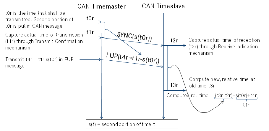
AUTOSAR and Time Synchronization over CAN

Image
If you are checking documentation from AUTOSAR about time synchronization over CAN you can get a bit confused by looking at figure 1. Here I’ll try to clear it out with some examples.    Figure 1 - CAN Time Synchronization mechanism

SP Racing H7 Extreme - IMSSBL

Image
 This is a demonstration GUI application and second stage bootloader for SP Racing H7 Extreme board PX4 version.  It is designed as cloner protection for STM32 boars so if you are looking for a solution on how to protect your board you can contact me. For now, this is an application that can help PX4 developers or any other developer using the H7 Extreme board. It works with IMFlasher GUI and console applications. 

Flashing/debugging/running code at external memory in the memory-mapped mode

Image
  STM32 microcontrollers have special capabilities running code directly from external flash. To make it possible STM32 made a special set of instructions called memory-mapped mode where the microcontroller is reading instructions from the external flash. Since to read data from an external flash can take some time there is QSPI protocol witch basically four wires used as SPI MISO (Master Input Slave Output) to make throughput 4x time faster than classical SPI.   Figure 1 - Illustration of STM32H750 connected to W25Q128JV 

Brushless motor kV: 4s vs 6s vs 8s vs 10s battery

Image
This just a simple image with a comparison of different kV(constant velocity) for different numbers of the cells in the battery.  On the left is RPM(Revolutions per minute) on what kV number your motor needs to have to achieve the same RPM number.  It is compared to 4 different batteries. 4s =  4 cells, 6s = 6 cells, 8 =  cells, 10 = 10 cells.  I know how to do this calculation for a long time but I want to have a picture that can be easily accessible over Google image search. This table shows only the RPM comparison. Lower kV motors usually have a stronger moment, because of the lower number of copper wire turns resistance is lower, so current is higher. Check also this video to get experience from first hand: https://www.youtube.com/watch?v=0H2gm6v6dZQ

Upgrade Taranis with RG405

Image
If you are planning to replace the original antenna in Taranis don't use RG178 or RG316. There is a much better solution! The RG405. RG405 is designed to go up to 40 GHz while RG178 and RG316 are labeled up to 3 GHz. With that in mind be sure that RG405 will perform much better at the 2.4 GHz at what Taranis radio operates. If you don't believe check it for your self: https://www.pasternack.com/images/ProductPDF/RG178B-U.pdf https://www.pasternack.com/images/productpdf/rg316-u.pdf https://www.pasternack.com/images/ProductPDF/PE-SR405TN.pdf In this datasheet, there is only 1 GHz test that we can use to compare cables. Here is the table: Name            Max freqency[GHz]          Attenuation at 1 GHz [dB/100m] RG178 3 145.7 RG316 3 124.67 RG405 40 72.18 From the table, you can see how RG405 has much less attenuation at 1 GHz then RG178 and RG316. Less attenuation and Teflon...

Cobra CP-2207 2600kV - rewinding

Image
If you were unlucky as I am, you probably burned out one of the expensive cobra motors that are not in production anymore. Luckily you can fix it as I did. So here it is how. You will need a new enameled copper wire. The original in my motor was 0.3mm but it was really hard for me to wire it on the stator so I selected the first thinner, and that was 0.28 mm. Whit tinner wire you are limiting max amperage of the motor, but with my flight stile, I didn't find it a problem yet. Before you remove all wires there is a good chance you burnt out only one phase, so do a visual inspection to make sure if that is the case (it was for me). The motor has 12 polls. This is how winding for the whole motor is done. Take your time to figure this out. The motor has 3 phases and they are connected in delta connection at the end. First, make sure you get a photo of each poll when you start removing the wire, otherwise, you will forget the way the turns where done. ...

QUAD SPI Logic Analyzer Saleae Plugin

Image
If you are looking for Plugin to read your QSPI data for Logic. Here it is! You can compile it and use it: https://github.com/Igor-Misic/saleae_qspi It will look like this: If you don't have time to compile it, you can buy a 64bit Linux library. You will just need to place it in the "Analyzers" folder of the Logic program and restart Logic. The price is 4.99 USD. If you will have any problems with purchasing contact me over this blog.

Coremark Platform - banchmark your MCU

Image
Recently we started a project based on Coremark. We name it Coremark Platform because the idea is to add support to many different MCUs so everybody can check how the benchmark is done and can easily port their MCU to see how will score.

A brief overview of drones flight control software

Image
A couple of days ago I have written a blog post for embeddedrelated.com with a brief overview of drone flight controllers. If you are interested in BetaFlight, PX4, Ardupilot, Paparazzi, CleanFlight, etc,  go and check this post: https://www.embeddedrelated.com/showarticle/1260.php

3 print screens explain how setup Eclipse with ST-LINK v2

Image
This setup is for STM32F103. Choose your STM32 in target link.

CMSIS Biquad Cascade IIR Filter + Iowa Hills IIR Filter Design

Image
You are looking at CMSIS IIR Filters ( https://www.keil.com/pack/doc/CMSIS/DSP/html/group__BiquadCascadeDF1.html ), and don't know how to use it? Don't worry, this example will clearly help you. The first thing that you need to know is that Biquad Cascade DF1 use this transfer function to do filtering. y[n] = b0 * x[n] + b1 * x[n-1] + b2 * x[n-2] - a1 * y[n-1] - a2 * y[n-2] It is hard to understand how this does filtering, especially if you looking at it in the time domain. In short this transfer function use current input(x[n]), and two last input(x[n-1], x[n-2]) and output (y[n-1], y[n-2]). Each new input function calculates new output and stores all the values. That is all that this filter does. The hardest part is to calculate coefficients b0, b1, b2, a1, a2, that is where Iowa Hills IIR  Filter Design jumps in. In this example, I'll do the band-pass filter for 1 Hz. In the image below you can see, what I selected at Iowa Hills IIR  Filter Design. N...

Pixracer (STM32F427) CoreMark Score

The score is 275.34 at 168 MHz clock speed. CoreMark Size    : 666 Total ticks      : 21786 Total time (secs): 21.786989 Iterations/Sec   : 275.393585 Iterations       : 536999700 Compiler version : GCC7.2.1 20170904 (release) [ARM/embedded-7-branch revision 255204] Compiler flags   :  Memory location  : STACK seedcrc          : 0xe9f5 [536999700]crclist       : 0xe714 [536999700]crcmatrix     : 0x1fd7 [536999700]crcstate      : 0x8e3a [536999700]crcfinal      : 0xa14c CoreMark 1.0 :  275.393585  / GCC7.2.1 20170904 (release) [ARM/embedded-7-branch revision 255204] / STACK STM32F427            = 275.393585/168[MHz] = 1.63 TM4C123GH6PM   = 101.1378/80[MHz] = 1.26 It looks like it is not pure MHz what matter in MCU speed.

Tiva TM4C123GH6PM scores 101 points on CoreMark

Image
Lately, on STM page I have found out they put Coremark scores on brochures for the microcontrollers.  I was wondering what competitors scores, so I couldn't find anything for Texas Instrument. On https://www.eembc.org/ I have found out there is a source code of Caremark which can be ported on any platform, so I decided to port it on Tiva TM4C123GH6PM and test it. Here are the results: 2K performance run parameters for coremark. CoreMark Size    : 666 Total ticks      : 19775 Total time (secs): 19.774999 Iterations/Sec   : 101.1378 Iterations       : 2000 Compiler version : GCC7.2.1 20170904 (release) [ARM/embedded-7-branch revision 255204] Compiler flags   : Memory location  : STACK seedcrc          : 0xe9f5 [0]crclist       : 0xe714 [0]crcmatrix     : 0x1fd7 [0]crcstate      : 0x8e3a [0]cr...

ARM sinus lookup tables 5x faster than math.h - TM4C123GXL Cortex M4F

Image
Lately, I was working with IIR filter so in CMSIS repo I saw look-up table with sinus value. I was wondering how much faster it works then math.h sinus function. The name of the function which uses a lookup table is arm_sin_f32() which is part of  arm_math.h Lets first compare results calculated with the lookup table and math.h sin function. Result2 are from the lookup table (arm_sin_f32() -> arm_math.h) and result1 are from sinus function (sin() -> math.h). From results is seen that after decimal point 4-5 digits are similar so take care with that.  I have done an iteration of 100 000 calculation and I was measuring the time needed for math.h sin and got 9726 [ms], and for arm_math.h 2006 [ms] which is almost 5x time faster.  In the photo below I added sinus wave for both calculations. Blue is result1 and red is result2. You can see they overlap.  You can check the code on the link . 

Patch PCB antenna 7 dBi WiFi

Image
Recently I was looking for a small lightweight, at least 6 dBi gain antenna. At mouser web page I have found 25x25x4 mm patch ABRACON APAKN2504-S2448-T antenna for PCB with 7 dBi gain. I was surprised by this very nice antenna design. So I order two of them. When they arrived I was not sure how to connect to WiFi device so I started googling. There was no any special explanation how to connect it on the 50 Ohm cable, only how to connect it with 50 Ohm impedance PCB link. So I decide to connect it this way with 50 Ohms pigtails. After I connected it, I have tested it with a WiFi router, and they work very well. Figure 1 - Soldered antennas Figure 2 - Front side of antennas Figure 3 - Testing antenna with WiFi router  I will use the antenna with the u.fl connector together with CC3220SF-LAUNCHXL :)

Eclipse + Black Magic Probe + Embsysregview

Image
Is there a chance to use the Black Magic Probe with Eclipse and see the peripheral registers. Short answer: Yes it is. For peripheral registers, you will need the Embsysregview Eclipse plugin. If you have a problem to install it check my last blog post .  How setup BMP? Go to: Run -> Debug configurations -> GDB Hardware Debugging and select New Launch configuration on the top left corner. Select everything as it is on images (my example is for miniblink, you do it for your). Image 1 - Main

Embsysregview - Eclipse plugin and how to install it

Image
In the last couple of days, I was trying to install Embsysregview for my Pixracer (STM32F427VI) to do debugging with Black Magic Probe, but it wasn't possible to install it because there is a problem inside download links when you trying to do it over Eclipse marketplace. Image 1 - Error when you try to install Embsysregview from Eclipse market

Cortex-debug powerful extension for VSCode

Image
In the process of working on a new example (timer), I had some difficulty to make it work. I've found out it that my current setup for Black Magic Probe doesn't work with interrupts. Luckily, in the process of debugging I have found a very useful tool for debugging Cortex MCUs which supports Black Magic Probe debugger and with it, everything works much better because it has preloaded setup for BMP. The name of the extension is  Cortex-debug . In the time of writing this text version, 0.1.21 doesn't support powering board over BMP (monitor twpr enable) so I modified the source of the extension to enable it. Link to the modified extension is here . If you are Linux user you need to unpack this zip in to /home/your_user_name/.vscode/extensions/ and restart VSCode. Now your Pixracer (or other board) will be power up before you start debugging it. Another useful thing you can do is to add a static name to your black magic probe instead check i...

Example - miniblink on Pixracer

Image
I have created my new repo pixracer-examples in the hope I'll find a time to create as much as possible examples for Pixracer. For now, I've created miniblink. Link to repo: https://github.com/Igor-Misic/Pixracer-examples Editor: Visual Studio Code (include building and debugging config) Debugger: Black Magic Probe

Config for VS Code debugger and Black Magic Probe + Pixracer

Image
Maybe you like VSC but you don't know how to config. I have tried many different configs and find out this work best for me. I have tested it with miniblink from libopencm3 . Configuration: { "version" :  "0.2.0" , "configurations" : [ { "name" :  "(gdb) Launch" , "type" :  "cppdbg" , "request" :  "launch" , "miDebuggerPath" :  "arm-none-eabi-gdb" , "targetArchitecture" :  "arm" , "program" :  "${workspaceFolder}/miniblink.elf" , "args" : [], "stopAtEntry" :  false , "cwd" :  "${workspaceRoot}" , "environment" : [], "externalConsole" :  true , "MIMode" :  "gdb" , "setupCommands" : [ {  "text"  :  "target extended-remote /dev/ttyACM0" }, {  "text"  :  "monitor tpwr ...

Pairing TM4C123GXL with VL53L1X and VL53L0X

Image
Here is the git repo where I paired two Time of Flight (ToF) sensors VL53L1X and VL53L0X to the TM4C123GXL development board.

How connect Pixracer with Black Magic Probe

Image
Here is how to connect your Pixracer with Black Magic Probe. You can see images with proper wiring.

Why invest in Croatia

Image
 There is a lot of money fluctuating around, looking for good investment opportunity. But a good percentage of them finish nowhere? In last year I explored a little bit Croatian embedded situation and people inside that field. I discovered one precious information. You can buy all Croatian embedded people very cheap! If you have a good idea and the extra money you can easily open company in Croatia, set salary price over average Croatian salary in this filed and you will have all those people in your company. And what is the best part? you will pay that the half price than in the US or in western Europe! The only thing you need to have is money, a good idea and good knowledge of creating a Business and you are ready to create a large technology company. The average salary in Croatia for the embedded software developer is under  32480 € gross with all expenditures to the state. And believe me, Croatian developers are good developers. As example you can see c...

EK-TM4C123GXL - Configure the I2C Module to Transmit a Single Byte as a Master

Image
Name of this blog post is the name of chapter 16.4.1 from ARM Cortex M4 TM4C123GH6PM  microcontroller datasheet (MCU on EK-TM4C123GXL board). It will be showed how to setup I2C1 from scratch. There is a way to do this with functions for set registers parameters but in this blog post, it will be done by writing directly into the register address. It is decided that way because it is the way how drivers are done.   The EK-TM4C123GXL has support for 4 I2C serial computer buses. First, we need to unlock GPIO_PORTA register and I2C1 register. To do that we need to do that over System Control Register addresses.   Image 1 - System Control Register Map 1. Enable the I2C clock using the RCGCI2C register

Inside Turnigy AE-65A

Image
If you are trying to flash your Turnigy AE-65A ESC but you are not sure what MCU is inside, here is the answer. Inside is Silicon Labs C8051F310 MCU, the same one as inside Turnigy AE-45A. So that means you can flash it with BLHeli firmware for 45A version? I'm pretty sure the answer is yes but I didn't test it yet. If I do that I will post it here. Here are some pictures from inside. I have checked pinouts and they are same as those on AE-45A. Image 1 - C8051F310 with pinouts for C2 interface Link to datasheet: https://www.silabs.com/documents/public/data-sheets/C8051F31x.pdf   Image 2 - C8051F310 Pinout Diagram Image 3 - before disassembling Image 4 - the bottom side of the upper part after disassembling